OUCC Proceedings 11 (1983)Corrosion for Cavers II: Corrosion of Alloy Karabiners |
OUCC Proceedings 11 Contents |
Andy Riley
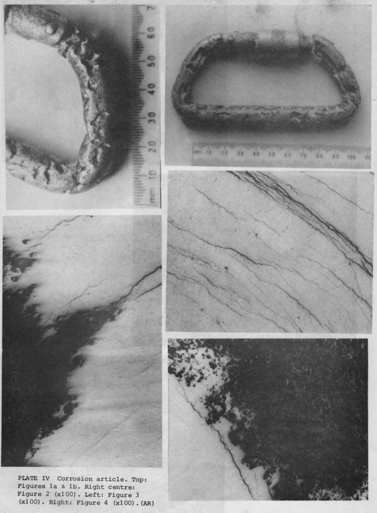
During a caving trip down Swinsto Hole, Kingsdale, N Yorkshire, a heavily pitted karabiner was found at the bottom of the 20 foot pitch lying under 0. 5 m of water in the gravel bed (Figures la and b).
The whole of the body of the karabiner was covered in pits several millimetres wide and deep. At the bottoms of the pits was a white, insoluble deposit. Only the screw-up gate was unaffected by corrosion. The unattacked parts of the surface did not show any more abrasion damage than would be expected to be caused by normal caving use.
A section
was made across the backbone of the karabiner which was hot-mounted in perspex
and polished to a 1 micron finish. Under optical examination, the entire section
was found to be full of cracks. This unexpected discovery led us to make further
investigations into the nature and origin of the cracks.
Under low
power observation, all the cracks were seen to run in circles, concentric with
the outer circumference of the section. The cracks were extremely numerous,
branched and finely divided (Figure 2). They seemed to be evenly distributed
throughout the whole section and were not located primarily at the surface. The
bases of some of the pits were examined. There was a definite orientation
dependence of the cracks to the base of the pits. In many of the pits, the
cracks were seen to emerge at the bottom (Figure 3), the pit growth direction
lying parallel to the crack direction. In other pits, the crack direction was
perpendicular to the direction of pit growth (Figure 4) and had not yet reached
the surface. All the pits had a deposit at their base. The aluminium metal at
the base of the pits showed signs of extensive corrosion attack and was very
spongy and porous in nature.
The
composition of the karabiner was unknown, but was determined by electron
microprobe analysis to be an Al-Zn-Mg-Cu alloy (see Table 1). An analysis of the
deposit in the base of the pits was attempted using energy dispersive analysis
(see Table 2). Wavelength dispersive analysis would have been superior but was
unavailable at the time of writing. The deposit was predominantly composed of
aluminium oxide.
Discussion of observations
The
chemical analysis suggests that the karabiner is a high-strength Al-Zn-Mg alloy.
Shreir (1976) suggests that these alloys have a high risk of suffering
stress-corrosion cracking which can be accelerated by incorrect heat treatment.
It seems likely that the surface pitting was probably initiated by the emergence
or interaction of the internal cracks with the surface. Once pitting has been
initiated, the pits grow unhindered by external effects or microstructure. This
is because pits generate an acid environment at their base which prevents
reformation of the passive film on the exposed aluminium surface (Robinson,
1960) and therefore corrosion proceeds rapidly. Impurities in the water can
assist in the initiation and propagation of pits - a combination of carbonates,
chlorides and copper ions can be very damaging (Davies, 1959). In hard water, as
little as 0.02 ppm of these ions can initiate pits (Porter and Hodder, 1953,
Rowe and Walker, 1961).
The
orientation of the cracks in the section strongly suggests that the
microstructure is exerting a major influence on their growth direction. The very
fine branched nature of the cracks suggests that they are intergranular.
Unfortunately, I was not able to etch up the grain boundaries in order to
demonstrate this. Exfoliation corrosion is a well-known phenomenon in high
strength aluminium alloys. Robinson has examined the effect of elongated grain
structure and heat treatment on the formation of surface blisters (Robinson,
1982). It seems likely that an elongated grain structure is formed in the alloy
karabiner during manufacture as it is extruded and that this initiates surface
and filiform attack. Grain boundary attack then causes the production of
corrosion products, creating large stresses at the grain boundary which force up
grains at the surface to create blisters. If these blisters reach a certain
size, a pit will form and pitting corrosion will dominate.
Conclusion
Grain
boundary attack has probably occurred because of precipitation and segregation
of alloying elements at grain boundaries during heat treatment. Exfoliation
corrosion produced blisters on the surface which in turn caused deep and severe
pitting. The intergranular attack and pitting in this karabiner has become
apparent due to its immersion for an unknown time in cave water which might be
expected to contain the necessary impurities for this kind of corrosive attack.
It would be interesting to know how long it would take for such attack to occur
and whether such slight attack which may occur during normal caving use has any
effect on the strength of the karabiner.
References
Davies, D.E., 1959. Pitting of aluminium in synthetic
waters. J. appl. Chem.
9, 651-660.
Porter, F. C. and Hadden, S.E., 1953. Corrosion of
aluminium alloys in supply waters. J. appl. Chem. 3,
385-409.
Robinson, F.P.A., 1960. Pitting corrosion - cause,
effect, detection and prevention. Corros.
Techno1. 7, 237-239, 266.
Robinson, M.J., 1982. Mathematical modelling of
exfoliation corrosion in high strength aluminium alloys.
Corros. Sci. 22, 775-790.
Rowe, L. C. and Walker, M.S., 1961. Effect of mineral
impurities in water on the corrosion of aluminium and steel.
Corrosion 17, 353t-356t.
Shreir, L.L., 1976.
Corrosion. Butterworth, London, 2 vols., 2nd edn.
Table
1.
Electron microprobe analysis
of karabiner alloy
composition
Standardless EDS analysis
(ZAF corrections
via magic V)
|
Element & line |
Weight % |
Atomic % |
Precision 3 sigma |
K-ratio |
Iter |
|
Al Ka |
92.54 |
6.77 |
1. 18 |
0.9279 |
|
|
Cu Ka |
1.11 |
0.49 |
0.34 |
0.0108 |
|
|
Zn Ka |
6.35 |
2.74 |
0.91 |
0.0613 |
6 |
+ ca. 1% Mg
Table 2. Electron microprobe analysis of
pit deposit composition
Standardless EDS analysis (ZAF corrections via magic
V)
|
Element & line |
K-ratio |
Weight % |
Precision 3 sigma |
Oxide formula |
Oxide % |
|
Al Ka
|
0.6654
|
37.40
|
1.10
|
A12O3
|
70.66
|
|
Si Ka |
0.0511 |
6.20 |
0.68 |
SiO2 |
13.27 |
|
S Ka |
0.0075 |
0.58 |
0.17 |
SO3 |
1.44 |
|
Ca Ka |
0.0168 |
0.77 |
0.18 |
CaO |
1.08 |
|
Fe Ka |
0.0358 |
1.42 |
0.36 |
FeO |
1.83 |
|
Cu Ka |
0. 1418 |
5.95 |
0.99 |
CuO |
7.45 |
|
Zn Ka |
0.0817 |
3.42 |
0.82 |
ZnO |
4.26 |
|
O* |
|
44.25 |
|
|
|
* - determined by stoichiometry